RealTimer
for RealTalk
|
| ReelTalk is a combination AM/FM radio and tape recorder. The tape recorder
operates at 1/4 speed, which means that you can record up to 220 minutes
on one side of a 110 minute cassette. If the program you wish to record
is longer than 220 minutes, you've got a problem. For example, Art Bell's
5 hour radio show doesn't fit on one side of a cassette (RealTalk doesn't
have an auto reverse feature).
|
| Enter RealTimer! RealTimer is a software application that turns AC
power on and off by using the computer's parallel printer port. RealTimer
can be programmed to turn the ReelTalk radio and tape off during station
breaks at the top and bottom of the hour and back on when the radio show
resumes! Art Bell's 5 hour show now fits on less than one side of a 110
minute cassette.
|
| This web page provides the source code and executable for RealTimer
and explains how to build the necessary hardware. A word of CAUTION is
warranted. This project involves working with hazardous voltages. It is
possible that such voltages could kill you. If you don't have basic electronic
skills, find someone to construct this project for you. I cannot take responsibility
for what you do; only you are responsible for what you do. So again, take
care when building this project or find a friend who has the proper skill
set.
|
 |
|
Click
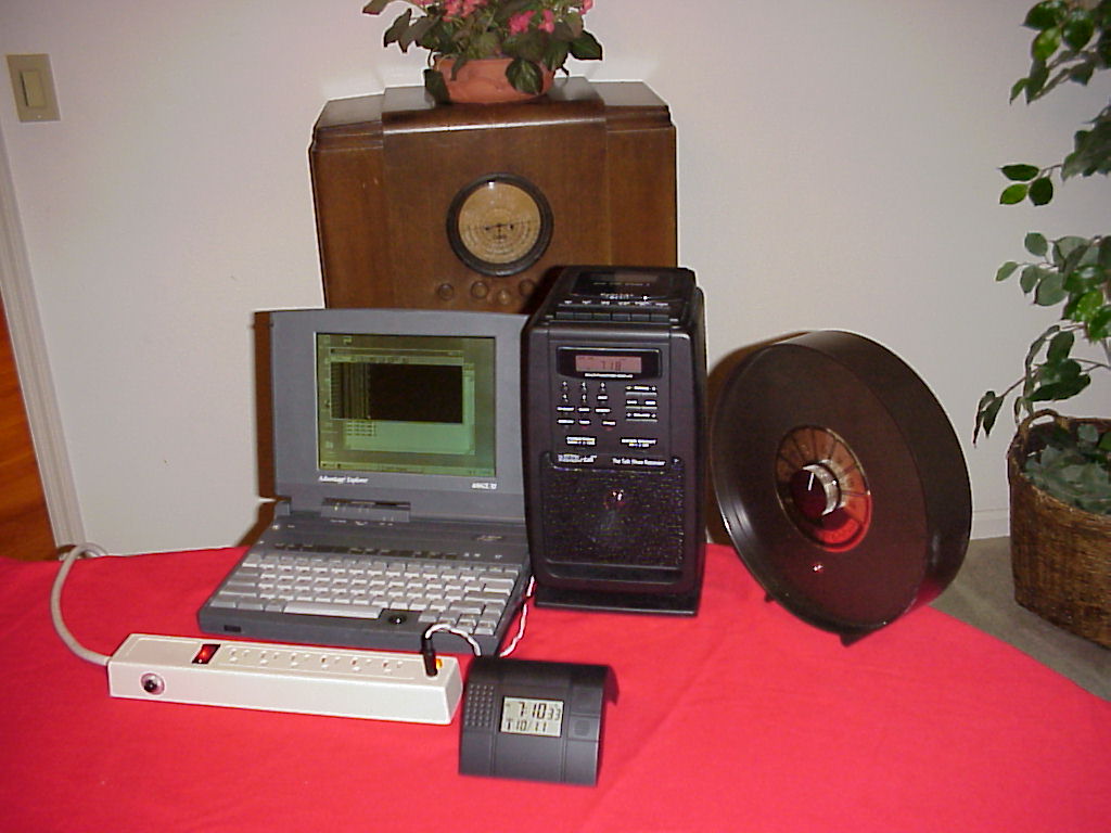
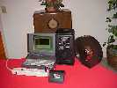
on the following picture to see a sample system. The Zeit
radio controlled clock monitors WWV and insures the laptop's
system clock operates with split second accuracy. WWV is
a radio station operated in Colorado, which serves as a time
and frequency standard with the accuracy of an atomic clock. |
|
| The Zeit clock keeps the laptop running on time. RealTimer software
running on the laptop outputs a signal to the parallel printer port that
controls three of the power strip's 6 AC sockets. RealTimer follows timing
instructions in a data file that tell it when to turn the AC power on and
off.
|
| The antique radio in the background is a Montgomery Ward Airline radio
that receives the standard AM band through the 16 meter band.
|
 |
|
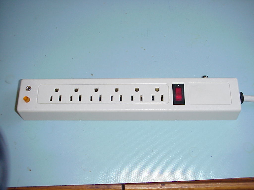
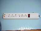
Here is a picture of a modified power strip. Click on the
picture to get a better view. Note the stereo mini-phone jack
and neon light on the left-hand side of the power strip. |
|
 |
|
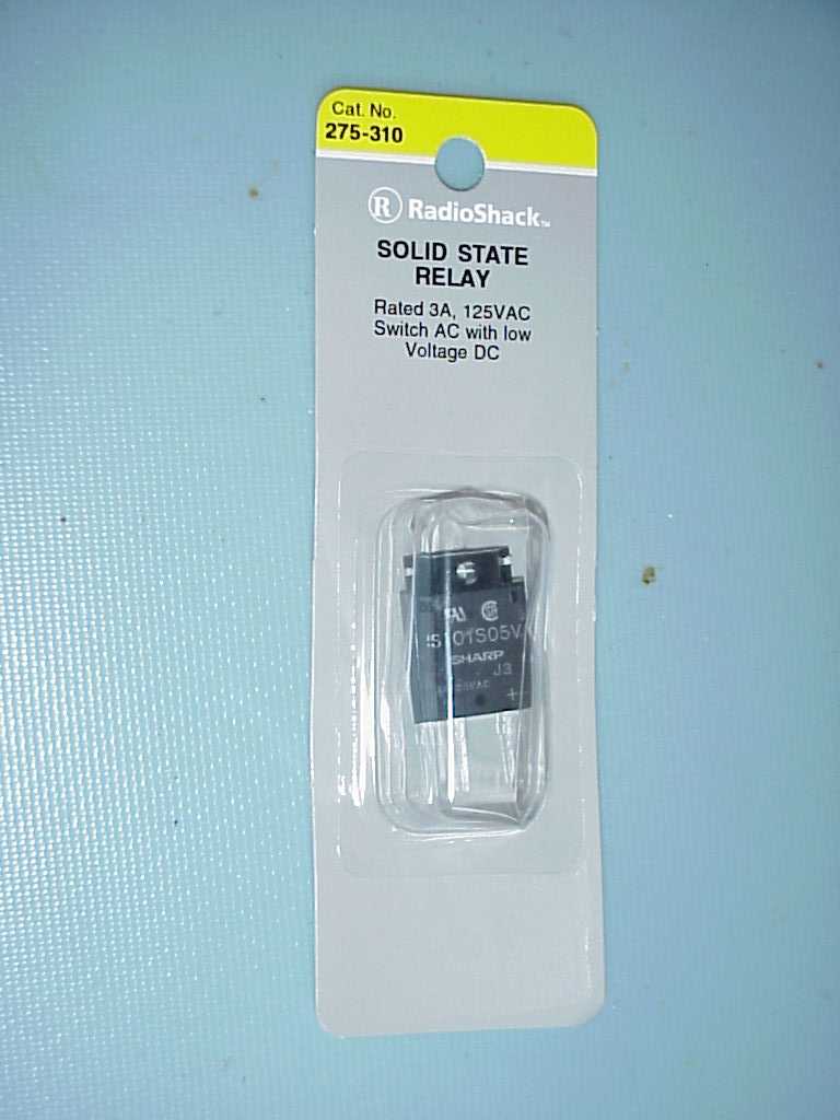
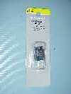
An opto-isolated triac is used to control the three AC power
outlets. Click on the following picture to see the packaged
opto-isolated triac. |
|
 |
|
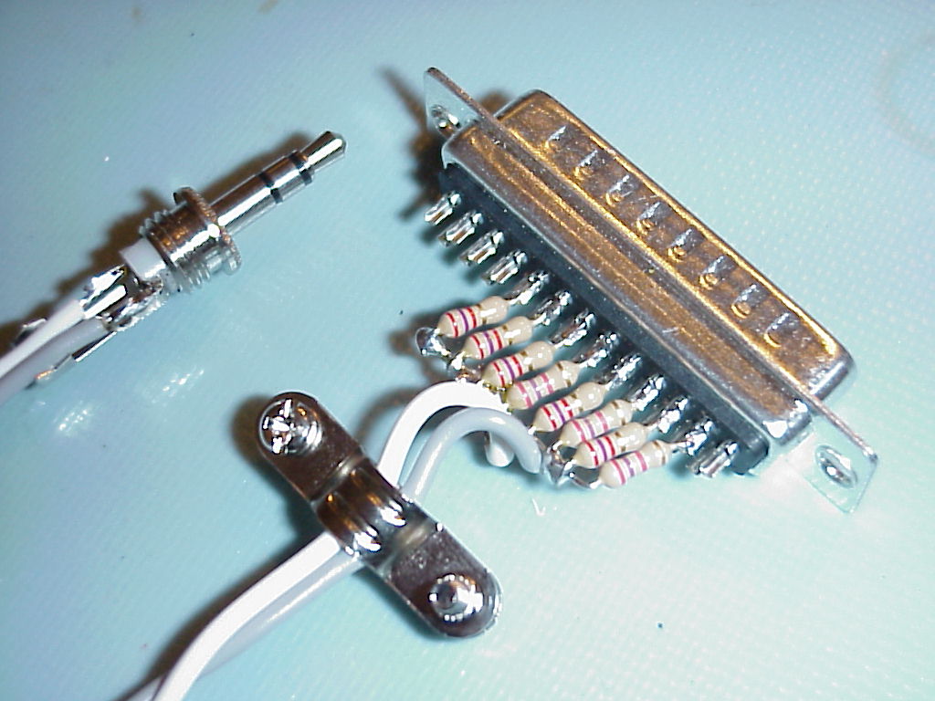
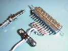
The computer's printer port is used to drive the LED inside
of the device. The eight printer data output lines are connected
in parallel through current limiting resistors to drive the
LED. Click on the following picture to see a better view of
the DB-25 parallel port connector with the eight resistors
soldered in place. |
|
 |
|
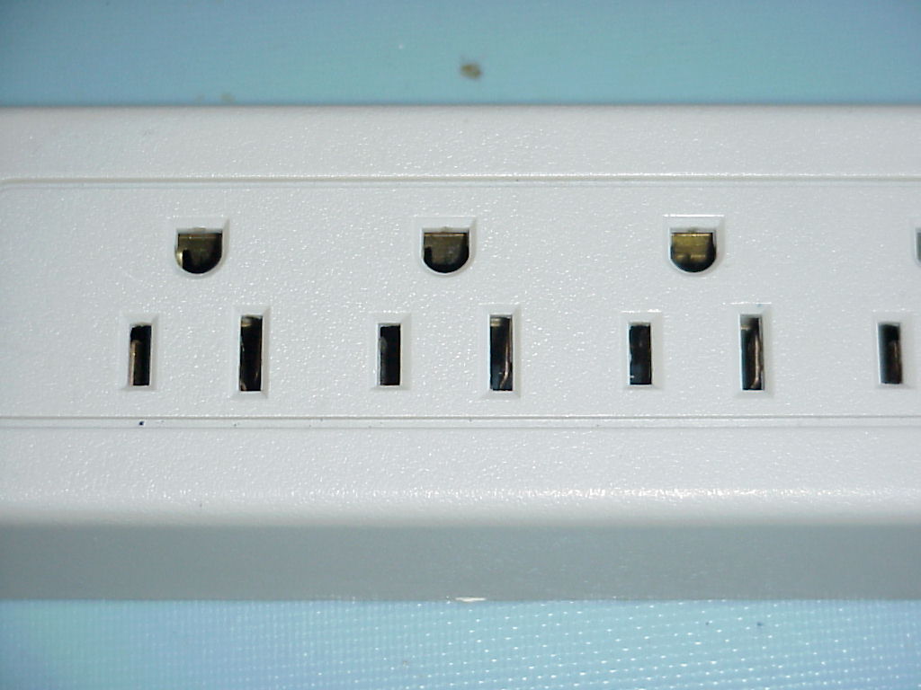
The three AC outlets that will be controlled by the opto-isolated
triac must be isolated from the other three AC outlets. Usually
three brass strips are used to make the hot, neutral and ground
connections with plugs inserted into the six AC outlets. The
'hot' brass strip that carries power to the last three AC outlets
must be cut so the opto-isolated triac can be soldered in.
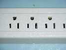
To help identify the 'hot' brass strip, look on the front of
the power strip. There are two cutouts per AC outlet where
the two flat 'blades' of the plug are inserted. Note that one
of the blade cutouts is shorter than the other. The shorter
blade of the two is where the 'hot' connection is made. The
neutral connection is made with the longer blade. Click on
the following picture for a larger view of the front of the
power strip I modified. |
|
 |
|
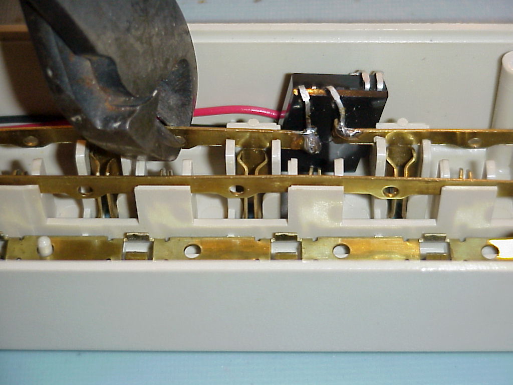
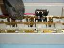
Turn the power strip over and cut the 'hot' bus (remember:
the short blade). Bend the edges of the brass bus so the leads
from the opto-isolated triac can be soldered to the bus making
both a good mechanical and electrical connection. Click on
the following picture to see a better view of the opto-isolated
triac I soldered into my power strip. In the picture the diagonal
cutters are positioned to demonstrate how I cut the bus. |
|
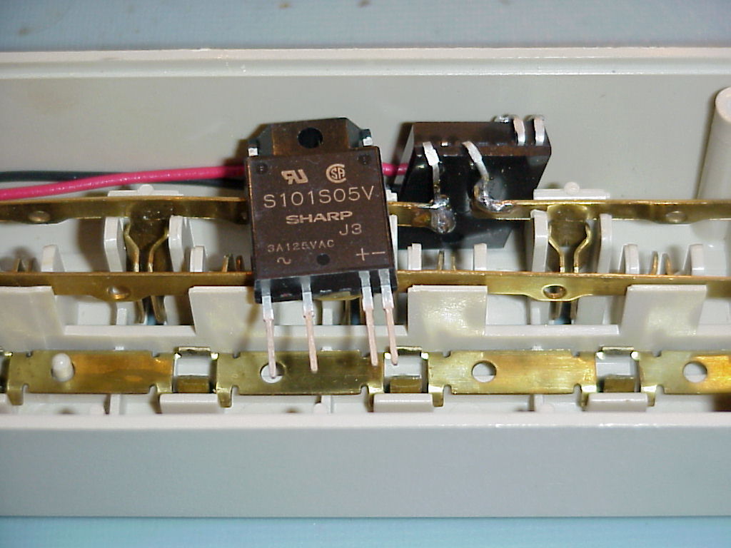
| Look at the opto-isolated triac and identify which leads are soldered
to the 'hot' bus, and which will go to the mini-jack. On the opto-isolated
triac that I used, the leads that will be soldered to the 'hot' bus (AC
load) had a tilde ('~') between them. The tilde represents alternating
current (AC). The two other leads, which go to the LED, were identified
with a plus ('+') and a minus ('-') sign.
|
 |
|
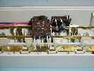
Click on the following picture for a close up of an opto-isolated
triac as it comes out of the package next to an installed opto-isolated
triac. |
|
| When positioning the opto-isolated triac in the power strip, make sure
to bend the LED ('+' and '-') leads so that there is no way they could
ever come in contact with any of the brass busses. Before doing any soldering,
make sure that all four leads are bent so that the opto-isolated triac
will properly fit in the power strip.
|
| Solder a red wire (or other suitable color) to the LED '+' lead and
a black wire to the LED '-' lead. Allow enough wire to reach the location
of the mini-jack.
|
| You will need to drill two holes in the power strip in order to install
the neon light and stereo mini-jack. Locate the neon light so that its
two wires can easily be soldered to the neutral and hot busses. Locate
the stereo mini-jack so that after the black and red LED wires are soldered
on, there is no way any hazardous voltages can come into contact with them.
|
| After the neon light and mini-jack have been installed, prepare to
solder the opto-isolated triac into place. Route the LED wires so they
are out of the way of all busses and plug openings. The wires should lay
neatly along the side of the power strip. Insure that the wires will not
be trapped or squeezed when the power strip base is reinstalled.
|
| Before soldering the opto-isolated triac into place, you may wish to
fold the brass bus over the triac leads to make a solid mechanical connection.
Now solder the opto-isolated triac leads to both side of the 'hot' bus.
|
| Now solder the LED wires to the stereo mini-jack. The stereo mini-jack
has three connections called tip, ring and ground. The tip contact is the
connection that makes contact with the very tip of a stereo plug. The ring
is the connection which is between the tip and ground connections. We will
be connecting the red LED wire to the tip contact and the black LED wire
to the ring contact. The ground contact will not be used.
|
| Now solder the two wires from the neon light to the 'hot' and 'neutral'
busses. Don't solder either wire to the round bus.
|
 |
|
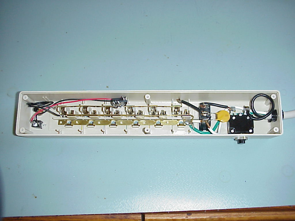
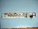
Click on the following picture to see a bigger view of my
completed power strip. Note the yellow disk on on the right
side of the power strip between the switch and the circuit
breaker. |
|
| The yellow disk that you saw in the picture above is a metal oxide
varistor (MOV). This is the device that suppresses power line surges. On
my power strip, the MOV was located on the left side of the power strip
where the neon light and mini-jack are now located. I moved it to its present
location so I'd have room for the neon light and mini-jack, but more importantly
I moved it so that it would not be switched 'in' and 'out' of the circuit
by the opto-isolated triac. Had I left the MOV in its original position,
power surges would have traveled through the opto-isolated triac--bad idea.
|
| Reassemble the power strip. Test that three of the outlets provide
power to your radio and the other three don't. With nothing connected to
the three switched outlets, you may notice a very dimly lit neon light--this
is normal. A neon light takes so little power that leakage current through
the opto-isolated triac may cause it to be dimly lit or flicker.
|
| The final step is to make a cable to connect the power strip to a computer's
parallel port.
|
| Add RealTimer software to control the outlet, and voila! Ready to go!
|
| Here is the source,
executable and sample schedule file (RealTimr.zip --
28 kBytes). This program was extensively used under Windows 95. It
should work fine under any Windows 9x but it will not work under
Windows NT as it issues IO writes directly to the parallel port.
This program has been successfully modified to run under FreeBSD. |